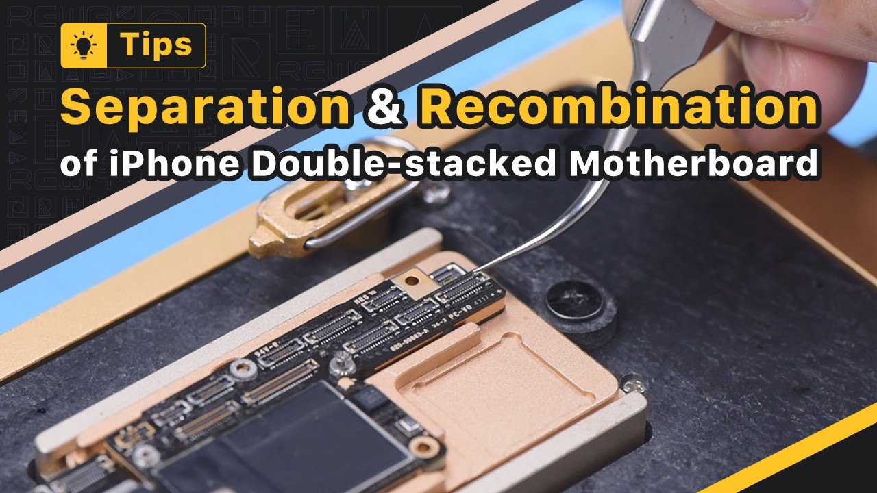
Recently, REWA Academy students offered comments that both layers usually fail to fit carefully in double-stacked motherboard repair work There are also big gaps, causing quasi soldering In action, we will certainly share ideas and notes when dividing as well as recombining double-stacked motherboard Peel foam on the motherboard prior to heating Please be noted that we do not recommend beginners to heat the motherboard with a warm air weapon Since the motherboard might get heat erratically as well as warp A professional motherboard heating platform is what we suggest To promote later on elimination of the reasoning board, drive a screw on the reasoning board Cut with the tape with a Sculpture Blade The logic board and also center layer are soldered with low-temperature solder paste So the ideal temperature for the heating system will certainly be 155 ° C-165 ° C Push the logic board gently with tweezers when the temperature level reaches 165 ° C If the reasoning board hangs, the tin has actually melted Clamp the screw to get rid of the logic board Get rid of the signal board Remove thermal oil with a Sculpture Knife Thermal grease must be gotten rid of totally Or else, the thermal grease will certainly touch the reasoning board to generate pseudo soldering in recombination Affix the signal board to the holder Apply a round of Paste Change Eliminate tin on the bonding pad with Blowpipe at 365 ° C and also Solder Wick Tin on the bonding pad must be entirely removed The recurring tin will certainly affect the succeeding soldering Tidy the bonding pad with PCB Cleanser Clean the logic board with the exact same technique Please do not harm components around the bonding pad of the reasoning board while cleaning It is required to inspect if the bonding pad is neat after cleaning Connect the signal board to the Reballing System Placed the reballing pattern ready to see to it that it is pushing against the signal board To avoid the solder paste from streaming right into the motherboard gap, put a steel plate Apply a layer of low-temperature Solder Paste Rub out excess solder paste with a Lint-free Wipe Get rid of the reballing pattern Inspect if solder paste on the signal board is complete While applying solder paste, please make certain that solder paste should have a certain moisture If the solder paste is as well dry, it will certainly comply with the reballing pattern when the stencil is gotten rid of Because of this, the solder paste on the signal board will certainly not be uniform, which can conveniently lead to poor soldering Placed the signal board on the 165 ° C Home heating Platform to heat Stop heating after the solder spheres are formed Apply a percentage of Paste Flux after the signal board has cooled Align the logic board with the signal board Maintain home heating on the 165 ° C Heating System When the solder flux spills as well as reasoning board sinks, push the reasoning board gently with tweezers to make certain both layers fit carefully The push should be gentle and little Clean the motherboard with PCB Cleaner after the motherboard has actually cooled down If you find the motherboard flawed while recombining, you can put the motherboard on a level board as well as fasten it with a rubber band Press two sides of the motherboard gently To avoid crushing parts, please put a soft paper under the motherboard Following, we will share one more recombination approach The approach can be taken if the center bonding pad is not harmed When the tin melts, eliminate the reasoning board in a vertical fashion with tweezers It can be seen that there is a metal pad of 0.05 mm density around the signal board at a particular distance This metal pad is created to maintain a 0.05 mm void between the logic board and also the middle layer, protecting against the solder spheres from linking while soldering You only require to get rid of thermal grease on the motherboard when the repair is done Keep initial tin on the bonding pad Use a tiny quantity of Paste Flux Finally, line up the logic board with the signal board When the temperature gets to 165 ° C and the tin melts, transform the power off Press 2 ends of the logic board with tweezers until the motherboard has actually cooled down The logic board as well as the signal board fit very closely in this method There will be no connecting and solder spheres spillover Check out REWA Academy if you desire to find out more fixing abilities We have complete program packages for motherboard diagnosis and fixing ability improvement Click the link in the comment area to buy motherboard fixing program bundles Thanks for viewing as well as feel complimentary to leave a remark